Example Architectures
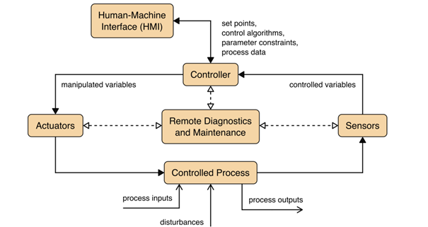
A typical OT system consists of control loops, human-machine interfaces (HMI) and remote diagnostics and maintenance tools like depicted in the image below.

Source: NIST SP 800-82r3, p. 11
A control loop is meant – as the name suggests – to control some kind of process. To do so, the loop employs a combination of sensors, actuators and controllers. Sensors measure certain physical properties like temperature or pressure and send these controlled variables to the controller. This component acts as the brain of the loop. By interpreting the sent information based on a control algorithm and target set points, so-called manipulated variables are created. These are sent to the actuators, which are the components that directly manipulate the controlled process according to the commands of the controller. For example, a sensor that measures the temperature of a boiler sends the controlled variable temperature to the controller. If the controller determines that the measured temperature is below the set target, he instructs an actuator to activate the heater rod of the boiler until the temperature matches the set target temperature again.
This process can mostly be monitored and manipulated by human operators via the so-called HMI. In our example the HMI maybe allows the operators to change the target temperature and to observe the current state of the boiler. Finally, remote diagnostics and maintenance tools can be used in case of abnormal operation of the system or solution.
Purdue Model
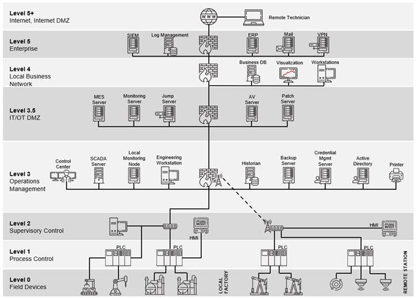
While this control loop gives a general overview of the principal function of a control system, not all OT systems and devices are equal. While some like PLCs are more involved in direct control of individual processes, others are used on a higher level to monitor and control whole ecosystems. An example for such a high level system would be a geographically distributed SCADA system used to monitor and control a complex infrastructure like a power grid. To get a better conceptual understanding of the different OT technologies, the Purdue Reference Model can be used. This hierarchical model depicts the data flows in ICS networks and is composed of several layers. While initially deployed in the 1990s, the Purdue Model today exists in many slightly modified versions, but in general there are 6 separate levels and additional DMZs between them. The image below shows these levels starting with Level 0 (the actual physical field devices) up to Level 5, where the enterprise IT resides. It can be seen that when going up the levels, the corresponding devices scope gets broader. While Level 0 and Level 1 are limited to the direct process (“shopfloor”), Level 2 already comprises a whole local station.

Source: Limes Security ICS.211 Industrial Security Training Advanced Technical Expert, p. 345
It has to be noted that the Purdue Model should not be seen as a strict, universal architecture, but a reference to think about how the overall system can be structured and where trust boundaries can and should occur. Nonetheless, the diagram above already shows one crucial security consideration in OT: The segmentation and separation between IT and OT (in this case realized by Level 3.5 IT/OT DMZ). As most security incidents still occur in IT, it is of utmost importance to prevent such an incident to spread to OT.